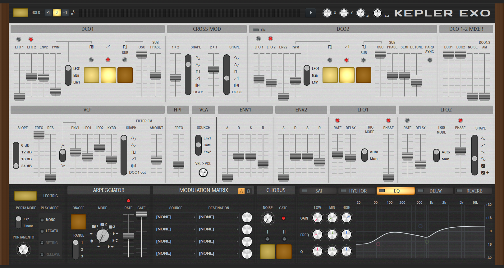
INSTRUMENTS / GENERATORS
Kepler Exo 
Kepler Exo imagines the world where the JUNO-6™ and Jupiter-8™ Synthesizers would have been, if they were conceived in the age of the plugin instrument. Very careful attention was paid to analyzing the oscillators, filters and interaction of the controls to make a sound that does justice to the original classics. Related plugin: Kepler.
There are controls...
Controls
Top Controls
- Hold - When activated holds the notes as if you wouldn't release the keys on the keyboard
- Octave - Transpose the sound by -1, 0 or +1 octave.
- Menu:
- Arp 1st Step Quantize - Arpeggiator playback will always be quantized to steps, i.e. Starts on next step.
- Theme - Choose from one of the available color schemes.
- Volume (Knob) - Master output level.
- Pan (Knob) - Master panning (position in the stereo field).
Arpeggio
- Arpeggiator On/Off - Activates or deactivates the Arpeggiator.
- Mode - Pitch cycle direction. Up, Up & Down, Down).
- Range - Octave range (1 to 3).
- Rate - Sets the playback speed of the Arpeggiator. Use the red LED switch above the slider to synchronize to song tempo.
- Gate - Note length.
LFO 1 (Low Frequency Oscillator)
- Rate - LFO Speed. Use the red LED switch above the slider to synchronize to song tempo.
- Delay Time - Time it takes for the LFO to fade in. The fade is linear.
- Auto / Manual (Trigger Mode) - When Auto is selected the LFO is retriggered on the first key press. When Man is selected the LFO is retriggered using the button below the Auto/Man selector. This is only audible when the Delay Time parameter is non-zero.
- Phase - Point in the cycle where the LFO waveform starts upon first key press. The bottom of the scale is 0 degrees, the top 180 degrees. NOTE: The Phase slider only has an effect if the red LED switch above is active!
LFO 2 (Low Frequency Oscillator)
- Rate - LFO Speed. Use the red LED switch above the slider to synchronize to song tempo.
- Delay Time - Time it takes for the LFO to fade in. The fade is linear.
- Auto / Manual (Trigger Mode) - When Auto is selected the LFO is retriggered on the first key press. When Man is selected the LFO is retriggered using the button below the Auto/Man selector. This is only audible when the Delay Time parameter is non-zero.
- Phase - Point in the cycle where the LFO waveform starts upon first key press. The bottom of the scale is 0 degrees, the top 180 degrees. NOTE: The Phase slider only has an effect if the red LED switch above is active!
- Shape - Choose from one of the waveforms indicated. The Random + Glide waveform is special in that it slowly glides from one random value to the next instead of immediately jumping from one value to the next as in the Random mode. Otherwise, movement is as indicated by the waveform shapes.
VCF (Voltage-Controlled Filter)
- Freq - sets cutoff frequency of low-pass filter
- Res - sets resonance of low-pass filter
- VCF polarity - sets polarity of envelope (positive or negative influence on cutoff frequency)
- Env - sets amount of the envelope influencing the low-pass filter's cutoff frequency
- LFO - sets amount of the LFO influencing the low-pass filter's cutoff frequency
- Kybd - sets amount of keyboard pitch influencing the low-pass filter's cutoff frequency
- Filter Shape - - This enables FM (Frequency Modulation) of the filter cutoff via DCO 1’s output or selectable waveforms running at the same speed as DCO 1.
- Slope - Choose from 6 to 24 dB per octave
- Filter FM (Frequency Modulation) - Adjust the amount of FM applied to the filter (see parameter Filter FM Shape).
Chorus
- Noise - Adds a noise to the output signal but only when one or both of the Chorus modes are selected.
- I - Emulates the Juno 6 Chorus I.
- II - Emulates the Juno 6 Chorus II.
- Chorus I+II - (Shift+Click) the disabled Chorus mode to engage both modes. This is possible on a Juno 6 Chorus by pressing Mode I and II together. Originally a 'hack' to obtain a third Chorus mode, probably not planned by the manufacturer.
VCA (Voltage Controlled Amplifier)
- Source:
- Env 1 - Env 1 controls the VCA.
- Gate - Gate controls the VCA. Sound is only heard when a note is held.
- Env 2 - Env 2 controls the VCA.
DCO 1 & 2 (Digitally Controlled Oscillator)
The Oscillator can create three different waveforms including a Pulse, Saw and Square wave. The Pulse waveform deserves some extra attention. It's like a Square wave, however the negative phase of the cycle can be flipped to the positive polarity and progressively along the length of the negative cycle. This keeps the pitch constant but the harmonic content or tone changes.
- LFO 1 & LFO 2 - How much the LFO 1 and LFO 2 modulates pitch. When activated (switch above the slider) and used together the LFOs will be combined and can create less regular patterns.
- Env Amount - How much Env 2 modulates the pitch.
- PWM (Pulse Width Modulation) - This slider will change the pulse width of the oscillator when the DCO Pulse is activated. There are 3 options on how to change the Pulse Width (see next parameter). With a setting of 50% the PWM will sound like a standard square wave. This is a 'duty-cycle' of 50%, meaning that it is high for half of the period and low for half of the period. A pulse wave with a duty cycle of 25% would be high for 25% of the period and low for 75% of the period. A low duty cycle will produce a brighter, more percussive sound, while a high duty cycle will produce a smoother, more mellow sound.
- DCO PWM Source - When LFO is selected, the LFO will modulate the Pulse Width of the Oscillator by the amount set by the PWM Slider. There are three modulation source options:
- LFO - The LFO modulates the Pulse Width.
- Man - The PWM Slider will manually control the Pulse Width.
- Env - Env 1 will modulate the Pulse Width.
- Waveform Combinations - The oscillator can play a sum of up to 3 waveforms:
- DCO Pulse active - The oscillator plays a Pulse in addition to the other selected waveforms.
- DCO Saw active - The oscillator plays a Sawtooth in addition to the other selected waveforms.
- DCO Sub active - The oscillator plays a -1 octave Square Wave in addition to the other selected waveforms.
- DCO Sub Volume - Level of the Square Sub Oscillator.
- DCO Sub Phase - Phase of the Square Sub Oscillator oscillators waveform. Phase determines the waveform level at a point in time and also if the waveform is rising or falling at that time. Choose from 90 deg to 0 deg (The Juno 6™ and Juno 60™ have 90 deg while the Juno 106™ has 0 deg).
Additionally DCO 2 adds the following controls:
- Semi - Semitone offset relative to DCO 1.
- Detune - Detune relative to DCO 1.
- Hard Sync - Hard sync is a technique used to create a sharp, percussive sound. It works by forcing DCO 2 to restart its waveform cycle whenever DCO 1 completes a cycle. This causes DCO 2 to produce a distorted waveform that is rich in harmonics. NOTE: For Hard Sync to be audible, the pitch and phase of DCO 1 and 2 must be different. This is where the Semi and Detune controls become most effective.
DCO 1-2 Mixer
- Osc 1 & 2 - Control the level of Osc 1 and Osc 2 independently.
- Noise - Oscillator noise level (it's hiss!).
- Osc 1/2 AM (Amplitude Modulation) - The level of Osc 2 will modulate Osc 1 to create new harmonics.
HPF (High Pass Filter)
- Freq - Cutoff frequency of High-Pass filter. High-Pass filters remove frequencies below the cutoff.
LFO Trigger & Portamento
- LFO Trigger (Switch) - Enable or disable the LFO Trigger section.
- Porta Mode - Exp vs Liner. Exponential will glide more quickly as the pitch-distance increases to maintain a constant glide-time. Linear will take the same time regardless of distance.
- Portamento (Knob) - Glide time.
- Play Mode - How notes (keys) will change from one to the next based on playing style. For a key-press to be considered new, they must not overlap with any other note. Choose:
- Poly 1 - First pressed key - no glide, any further keys glide from last held key to the new key.
- Poly 2 - Glide from last pressed key to any new key.
- Mono 1 - No glide on first key. Only retrier Envelopes on the first pressed key.
- Mono 2 - No glide on first key. Always retrier Envelopes on each key pressed.
- Mono 1b - Same as 'Mono 1', but always glide on first key.
- Mono 2b - Same as 'Mono 2', but always glide on first key.
Cross Mod (Frequency Modulation)
Cross Mod is another term for true Frequency Modulation (FM). NOTE: The 'FM' popularized by the Yamaha DX7™ was actually Phase Modulation (PM) where the target oscillators phase (the 'carrier') was modulated, and not frequency (the oscillator pitch). In Kepler Exo's the frequency of DCO 1 or 2 is directly modulated by the frequency of other, as indicated below:
- 1 -> 2 - How much DCO 1 cross-modulates DCO 2.
- Shape 1 - The shape used for DCO 1->DCO 2 cross-modulation.
- 2 -> 1 - How much DCO 2 cross-modulates DCO 1.
- Shape 2 - The shape used for DCO 2->DCO 1 cross-modulation.
Env 1 & 2
Standard envelope controls as found on most synthesizers.
- Attack (A) - Time taken to reach the 'Hold' level. Short attacks will make a sharper more percussive sound.
- Hold (H) - Initial level at which the sound is played when a key is held.
- Decay (D) - Time taken for the level to decay to the 'Sustain' level.
- Sustain (S) - Defines the 'Sustain' level, when a key is held.
- Release (R) - Defines how quickly the sound decays to silence on release (note off), if at all.
Effects (EQ, Delay, Reverb & Mod)
Multi-bank effects chain.
EQ (Equalization)
3 Band parametric EQ:
- Low, Mid and High - Low (shelf), Mid (peaking) and High (shelf) bands.
- Q - Bandwidth of the filter.
- Gain - Amplitude of the filter (boost or cut).
- Freq - Cutoff Frequency, the frequency where the filter starts to act.
Delay
- Amount - Level.
- Time - The switch above the slider sets time to Tempo-Sync mode.
- R Point (Right Tap) - Right speaker's delay time (relative to left speaker's delay time).
- Feedback - Level of the echo sent back into the effect. More feedback, more echoes ...
- Tone - Filtering on the 'wet' output from the delay. Low-pass (left), OFF center, High-pass (right) filters on the final output. High passing the wet output can avoid a 'muddy' overpowering delay with a preponderance of frequencies.
- Stereo - Panning spread of the echoes.
- Blur - Level of the smearing effect on echoes.
Reverb
- Low Cut - Adjusts the low cutoff frequency. Use this parameter to remove low frequencies from the input signal before reverb is added.
- High Cut - Similar to Low Cut. Adjusts the high cutoff frequency. Use to remove high frequencies from the input signal.
- Pre Delay - Controls the delay time between the direct input signal and the first reverb reflection.
- Pre Feedback - Creates a feedback loop into the pre-delay.
- Size - Size of the virtual room being simulated. For realistic effects, the Room Size should be adjusted according to the decay time. Small rooms sound better with a short decay time, large rooms sound better with longer reverb times.
- Diffusion - Density of the reflections bouncing off the walls of the virtual room. A low diffusion setting makes the reflections sound more distinct and sparse, like closely spaced echoes. A high diffusion setting creates a dense series of reflections, so close they sound more like a constant decaying noise.
- Decay - Decay time of the reverb, this is the time it takes for the signal to decay to -60dB (1/1000 of the maximum amplitude). Use low decay times for small rooms and long decay times for large rooms.
- High Damping - Damping (suppression) of the high frequencies in the reverb signal. Damping refers to the rate at which the high frequencies decay. This effect causes the reverberant sound to become gradually muffled and warmer.
- Width - Stereo spread.
- Dry - Dry input level heard at the output.
- Early Reflection (ER) - Relative level of the first reflections in the reverb.
- Wet - Relative level of the reverberant (wet) signal.
Mod (Modulation Matrix)
Contains 8 banks of Modulation Source to Destination Target relationships. Check the menus for options under each.
- Source - Choose the data which will modulate (automatically change) the values of the Target control.
- Destination - Choose the variable to be changed by the Source.
- Modulation Amount (Knob) - Multiplier amount for the Source to modulate the Destination. From -100 to +100%. Left is negative, right is positive. 12 O'Clock is 0% (no modulation). Negative settings invert the modulation relationship to the Destination.
Plugin Credits: Daniel Schaack (code & design), Dario Sanfilippo (VCF modeling & DSP), Miroslav Krajcovic (interface).