INSTRUMENTS / EFFECTS
Patcher
Patcher loads as an instrument or effect and allows you to chain both instruments and effects into complete units for reuse in other projects. Set up your favorite instrument & effects chain for example. You can also use it to add unlimited effects or instruments in a single Channel or Effects slot. A Control Surface is automatically addedinto Patcher, so you can create custom interfaces for your patches to make them easier to use, and link parameters into adjustable controls in a multitude of different configurations. Related plugins: Control Surface, Fruity Layer, Fruity Formula Controller and Minihost Modular.
NOTES:
- The workspace is resizable - Drag on the window to resize OR drag an object to the edge of the workspace to auto-resize. Use the scroll-bars to navigate the space.
- Arranging - The Menu option 'Auto-arrange modules' creates module columns to represent multithreaded processing logic.
- Processing - Modules added at the same number of nodes (after the 'From FL Studio' node) are processed at the same time (multithreaded), modules at different node-depths columns are processed sequentially.
- Patcherize existing plugins - Use the Channel Button (Right-Click) Menu > 'Patcherize' or Hold (Shift) and drop Patcher over them.
- Open multiple plugin windows - Use (Alt+Left-Click) to open the plugin UIs.
Video Tutorials
Patcher Controls
Navigation
General Navigation
- Vertical Scrolling - (Mouse-wheel) scrolls up and down (when not fully zoomed out).
- Zoom Vertically - (Ctrl+Mouse-wheel).
- Zoom Horizontally - (Alt+Mouse-wheel).
- Zoom in Both Directions - (Shift+Mouse-wheel).
- Pan view - (Middle-Click) on the patcher map and drag.
Mini Map Navigation
The Minimap is a navigational aid, most useful when working with large projects at high zoom levels.
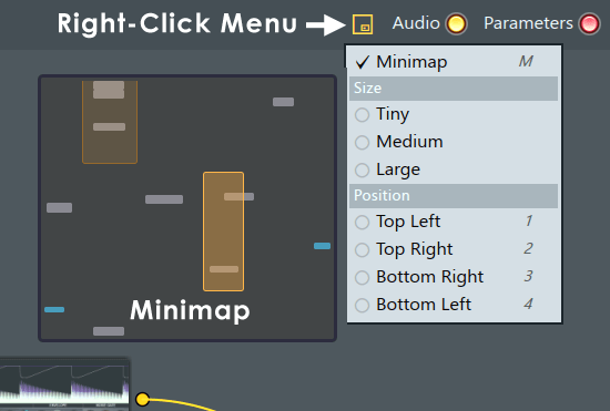
- Minimap Icon - Left click to enable/disable the Mini-map. The Minimap will show an orange rectangle representing the view-area. The more you zoom in (Mouse-wheel) on the Map. The Minimap view area will resize to represent the visible area. Click and drag the rectangle to move the visible area. (Right-Click) for additional controls:
- Size - Tiny, Medium or Large. You can also click the edge of the map and manually resize it.
- Position - Top Left, Top Right, Bottom Left and Bottom Right. You can also click on the Map of the Minimap (avoiding the selected area) and manually drag the Minimap to any location.
- Map components key:
- Zoom Regions - The Orange rectangles show selected or pre-defined zoom regions (the visible area in the Map window). (Left-Click) the regions to switch your view.
- Instrument/Effect nodes - Gray rectangles.
- FL Studio Input/Output nodes - Cyan rectangles.
- Minimap display shortcuts:
- Toggle map visibility - (m).
- Cycle sizes - (Shift+m).
- Map position - (1, 2, 3 or 4) predefined corner locations. 1 (top-left), 2 (top-right), 3 (bottom-right) and 4 (bottom-left). To manually position (Left-Click+Drag) anywhere outside the Zoom Region/s.
- Resize - Drag any corner of the map to manually resize.
- Minimap view keyboard shortcuts and gestures:
- Create a zoom region - (Ctrl+Right-Click+Drag) the area to view.
- Pan view - (Click+Drag) on a Zoom Region (orange square) OR (Middle-Click) on the patcher map and drag.
- Zoom both axes - (Ctrl+Alt+Middle Mouse-Click+Drag) horizontal and vertically.
- Zoom horizontally - (Alt+Middle Mouse-Click+Drag) horizontally.
- Zoom on mouse-position - (Mouse-wheel+Up/Down).
- Zoom out temporarily - (Double-Click) on empty Map.
- Zoom region 2 replace - (Ctrl+Right-Click+Drag) while zoomed out.
- Zoom region 2 return - (Double-Click).
- Zoom regions swap - (Ctrl+Right-Click) on the Map background.
- Zoom vertically - (Ctrl+Middle Mouse-Click+Drag) vertically.
Data Links Filters
(Left-Click) to switch filter groups On/Off. (Middle Mouse-Click) to Solo/Unsolo a filter group.
- Audio (yellow) - Shows Audio links (inputs & or outputs depending on the plugin).
- Parameters (red) - Shows internal automation parameter links (plugin program/interface controls).
- Events (green) - Shows note/event links (MIDI control data).
NOTE: Placing the mouse cursor over Link Nodes will show their name in the Hint Bar.
Working with links
- Make connections - Objects in Patcher have inputs on the left-side and/or outputs on their right-side. The connectors show as dots with colors that relate to the Parameter data type (see above). Click on any output or input connector and drag to a compatible connector (shown in green).
- Dragging to the Middle of an object - Will open a pop-up list of compatible link targets.
- Add / Remove connectors - (Right-Click) the FL Studio icons, plugins or parameters and activate/deactivate connectors.
- Automate plugin controls - You will first need to activate the controls Automation input to the plugin. These are not activated by default as there may be 100's of controls, and so 100's of input nodes. Proceed to link as follows:
- FL Studio native plugins - (Right-Click) the control and select 'Activate'. Then (Right-Click) it again and select Create Automation clip.
- VST & AU plugins - (Right-Click) the plugin and choose Inputs > Parameters and select the control. Then (Right-Click) the controls red node that appears on the plugin input side and select Create automation clip.
NOTE: Automation inputs show as a red node and do not have connection cables to the FL Studio input/output icons.
- Break a single connection - Left-click the input connector of a pair. Drag off the input into free space and release the mouse button.
- Change connections - Left-click the input connector point and drag to the new target input connector.
- Audio level - Click on the center arrow on a connection cable and drag vertically. The volume values are displayed in the Hint Bar.
- Mute audio - (Right-Click) the link.
- Right-Click nodes (and modules) - To see a popup with options, including to activate nodes, add links etc.
Events or MIDI to FX plugins
If you need to get MIDI data to an Instrument plugin that's loaded on Patcher in an FX slot, then:
- Load a MIDI Out channel and set it to 'Port 5', for example.
- Right click the 'From FL Studio' icon
- Select Patcher > Outputs > Events and activate 'Port 5'.
- Make the Event connection from FL Studio to the Plugin as normal.
Saving/Loading Patcher Presets
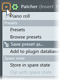
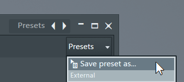
- To save a patcher preset - use the Wrapper Menu 'Save preset as' option. You can also drag this menu item to a new Channel or Effects slot to duplicate the current chain. Patcher is a great way to save your favorite Instrument & Effects chains ready for use in new projects.
- Encapsulate existing plugins - You can 'patcherize' existing plugins on a Channel Rack or Mixer Track slot by holding (Shift) and dropping Patcher onto the existing plugin. If you don't hold SHIFT the plugin will be replaced rather than encapsulated.
Tabs
There are two tab types. The Map which is the main workspace and layout window for the Patcher project and the Control Surfaces that hold internal controllers for the project. These can be renamed, right-click the control-surface icon on the Map tab, to better reflect their use. You can add as many Control Surfaces as you need to the project.
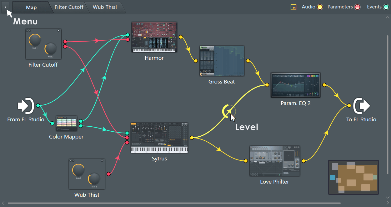
Map
The MAP tab allows you to build the plugin & or effects chain.
- Add plugins & controls - (Right-Click) the workspace and add from the pop-up menu - Plugins, Effects or a Control Surface.
- Opening plugins - As of FL Studio 12 plugins now open in 'detached' mode outside the Patcher UI when double-clicked (see below). NOTE: Plugin interface parameters are not right-click linkable or visible to FL Studio unless a GUI (interface) target has been right-clicked and 'activate' selected. Once this has been done a Parameter node for the control will also appear on the plugins Map tab icon. There are two ways to open plugins:
- Open a plugin and close all others - (Double-click) a plugin. This applies only to plugins open for that Patcher instance.
- Open a plugin leave others also open (Alt+Click) a plugin. This applies only to plugins open for that Patcher instance.
- Show data types - (Right-Click) the workspace and select from the pop-up menu the data types to be shown (including latency) OR use the Audio, Parameters & Events buttons along the top of the plugin.
- Rename objects - (Right-Click) the target object and select 'Rename' from the pop-up menu.
- Delete objects - (Right-Click) the target object and select 'Delete' from the pop-up menu.
- To add plugins - Use (F8) to open the Plugin Picker OR drag from the Browser > Plugin database to Patcher's Map tab window OR use (Right+Click) > Add plugin.
Right-Click Map Menu
- Show plugin picker (F8) - Opens the Plugin picker.
- Add plugin - Shows the Plugin Favorites list. Add plugins to this list using the 'F' (favorite) column in the Plugin Manager.
- View - Control the viewing of:
- Audio / Events / Parameters - Various data connections between plugins.
- Activity - Animations on connections that show data flow.
- Labels - Switch plugin labels, on or off, as shown below their icons.
- Latency - Shows a panel above the plugin with processing latency shown in ms. Latency compensation within Patcher is automatic.
- Performance - Use this to identify resource intensive plugins. Each module will show a CPU value in percent (above it) and a summary panel will additionally show:
- Total - The CPU total for the current instance of Patcher (sum of everything below).
- Patcher - CPU used processing the Inputs to and Outputs from Patcher (interfacing with FL Studio).
- Modules - Total CPU usage of all modules.
- Other - Internal CPU overhead.
NOTE: The CPU measures shown are based on the same metric used for FL Studio's main CPU meter. The percentage of the audio buffer length (time) required to create the audio for that buffer. The CPU percentages shown here, therefore, do not match the Operating System CPU meter, which shows the percentage of processing slots in use. See here for a detailed explanation.
- Auto-arrange modules - Do you trust us to arrange your modules for you? Click it if you dare. Multithreaded processing - This option also creates module columns to represent multithreaded processing logic. Modules in the same column are processed at the same time (multithreaded), modules in separate columns are processed sequentially.
- Hide all plugin windows - Hides all open Plugin interfaces from the current Map.
- Remember tab sizes - Individual tab sizes will be remembered as you switch between them.
- Link velocity - Links MIDI velocity to plugins on the Map that use it.
- Multithread plugins on this map - Switches on Multithreading for plugins on the current Map. Learn more about multithreading here.
- About - Shows Patcher version information, useful for Techsupport.
Control Surface
The Control Surface tab/s allow you to add real-time controls that can be linked to plugins in the Map chain. Parameter objects can be linked to plugins by Right-clicking the plugin on the MAP tab and activating a Parameter by Right-clicking on the plugin. (Right-Click) a control to automate it from this tab. You can add as many separate Control Surface tabs as needed to a project. In the image below there are two Control Surfaces, one has been renamed 'Wub this'.
NOTE: You can create your own custom controls with the Control Creator tool. (Right-Click) the Map and select Control creator to open it.
Working on the Control Surface tab:
- Add a Control Surface - The default Patcher loads with a single Control Surface, to add additional Control Surfaces drag from the Browser > Plugin database > Patcher > Control Surface and drop on Patcher. NOTE: If your plugin database is different, just search for 'Control Surface'.
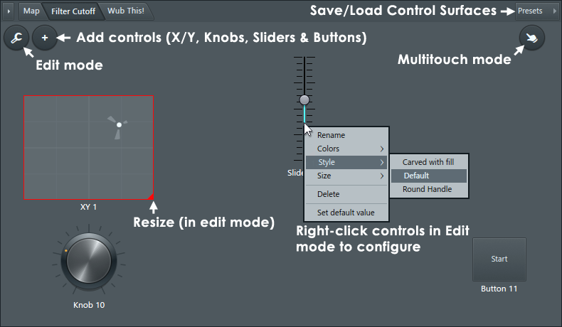
- Load/save Control Surfaces - Click the Presets button as shown above and either save or load a Control Surface configuration.
- Add parameter controls - Click the + (Add) button as shown above and select from the pop-up menu of controls.
- Edit parameter controls - Click the Edit icon as shown above (controls will show red-rectangles around them) then you can click and drag to move or right-click and select the size, style, colors and rename the control.
- Automate Native Parameters - From the MAP tab (Right-Click) the Plugin Icon and select 'Activate' from the pop-up menu. The control can be Right-clicked again and automated with the usual options such as 'Create automation clip' or 'Link to controller'.
- Link plugin parameters to Control Surface parameter controls
- 1. Add a Control Surface control with the + button or you can use an existing control.
- 2. Open the Map tab and drag FROM the controls related Parameter node on the right side of the Control Surface icon ONTO the middle of the target Plugin icon and release.
- 3. From the pop-up list select the desired GUI or plugin control target.
- Automate VST Parameters -
- 1. (Right-Click) the plugin on the MAP tab and select:
- 2. Inputs > Parameter and select the automation target Parameter from the pop-up list.
- 3. (Right-Click) the red Parameter Node that appears on the Plugin and 'Create automation clip', 'Link to controller' or 'Edit events' as usual.
- Rename Parameters - (Right-Click) the parameter and select 'Rename' from the pop-up menu.
- Live tweaking - Open the Parameter tab and use the mouse on the Parameter of interest as you would any plugin control. Select Multitouch to control multiple controls on a multi-touch monitor.
Patcher Voice Effects Plugins
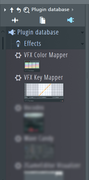 | To add VFX Note Mapper to the Patcher project, dragging from the Browser > Effects > Voice category and drop on the Patcher Map. For fast linking drop on the Events link into the plugin you would like to control. VFX can't be used in FL Studio Channel or Effects slots so they are not generally made visible in the plugin lists. The VFX plugins include: |
- VFX Color Mapper - Control up to 16 independent generators/instruments (or groups of generators) using the 16 note colors of the Piano roll.
- VFX Envelope - Control up to 16 independent envelopes x Velocity, Pitch and Pan. Plus Mod X and Mod Y, using the 16 note colors of the Piano roll.
- VFX Key Mapper - Note input can be transposed, made into a chord, key-changed or creatively remapped.
- VFX Keyboard Splitter - Split the Piano roll or keyboard zones into 16 separate outputs.
- VFX Level Scaler - Scale Note Properties as received from the Piano roll.
- VFX Sequencer - Transform chords into melodic phrases according to the pattern you program.
Adding Features
Patcher can be used to create setups with features equivalent to VST/AU plugins. By using the Fruity Formula Controller together with Patcher and Control Surface, you can create non-linear control behavior and add logic into how the surface controls operate and affect parameters. In this section there are a few examples of what types of features you can achieve.
Switches
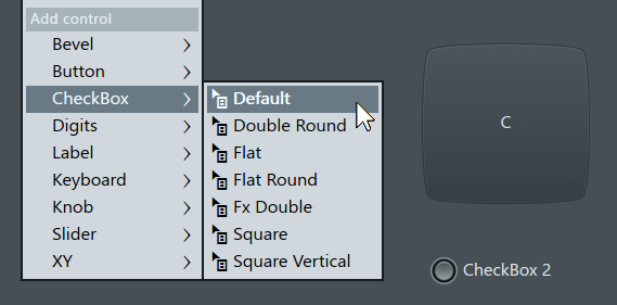
Control Surface has two types of controls designed to switch between two states (on/off), the Button and the CheckBox:
You can make a parameter dependent on the state of one or multiple switches by adding logic gates. An example of this is having two switches, and requiring both of them to be toggled on (AND gate) in order for something to happen to a parameter in the Patcher 'Map' tab. You can also make switches to change the functionality of a control to be something else, for example connecting the same knob into two parameters, but deciding which one it controls with a switch. Logic gates take 1 or more inputs, and based on the type of gate and the states of the inputs, outputs a specific result. Fruity Formula Controller can be used as a logic gate, and you can find the syntax for various different gates on the Fruity Formula Controller page.
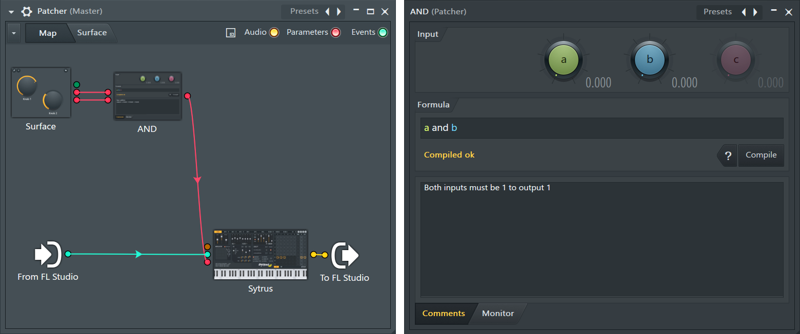
A simple AND gate example:
- Add plugins - You'll need a single instance of Fruity Formula Controller, and additionally a plugin you wish to control.
- Activate parameter(s) - Open the plugin, choose the parameters to be affected and activate them. (Right-Click) on Fruity Formula Controller, select Inputs > Parameters and make sure both 1. a parameter and 2. b parameter are activated. Finally, select Outputs > Controllers > 1. Out.
- Add switches - Go to the 'Surface' tab and add two CheckBoxes by clicking on the button with a plus icon and selecting 'CheckBox'.
- Connect controls - Return to the 'Map' tab and draw connections from the surface controls to the Fruity Formula Controller inputs, as illustrated in the example image above.
- Connect output - In a similar manner, draw a connection from the Fruity Formula Controller output into the input(s) of the plugin.
- Write a formula - Open Fruity Formula Controller, type 'a and b' into the formula input area and press compile.
- Test the setup - Go to the 'Surface' tab and make sure the plugin and parameter(s) are visible. Now you should observe that only when both CheckBoxes are on, the parameter(s) switch to 100%, and otherwise stay at 0%. You can also open the Fruity Formula Controller and see how the output changes in the 'Monitor' tab.
Selectors
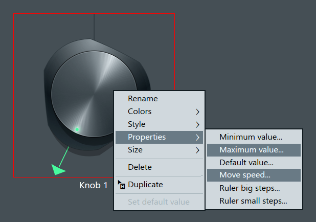
While certain surface controls like checkboxes and buttons can only have two states, you can create switches that have more than that by using other types of controls, like knobs, sliders or digit displays. This way you can create selectors that have the ability to switch between multiple states, for example a selector knob with 3 states that selects which audio path will be outputted. You can change the number of states by:
- Changing the minimum and maximum values - For a 3 state switch, set the maximum value to 2 by accessing the (Right-Click) menu of the control. The minimum value is at 0 by default, so the total amount of values is 3 (0, 1 and 2).
- Changing the move speed - The less values the control has, the more sensitive it is to the mouse movements, and will move very quickly from one extreme to the other. With a low number of states, set the move speed to 1.
NOTE: The minimum and maximum values of a control only determine the number of steps or states it can appear to have. It won't affect the actual range of the control, which will always be from 0% to a 100%. You can also set the minimum and maximum values into negatives, which can be useful when working with the 'Digits' control, which can display the values as negative.
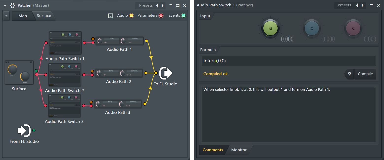
An audio path selector example:
- Add plugins - You'll need 3 instances of both Fruity Formula Controller and Fruity Mute 2. You'll also need the audio sources for each path, these could be generator plugins connected into different types of effect chains.
- Activate parameter(s) - (Right-Click) on Fruity Mute 2, select Inputs > Parameters > 1. Mute. (Right-Click) on Fruity Formula Controller, select Inputs > Parameters > 1. a parameter. Next, select Outputs > Controllers > 1. Out. Repeat this process for each instance.
- Add control - Go to the 'Surface' tab and create a knob with 3 states by clicking on the button with a plus icon and selecting 'Knob'.
- Connect controls - Return to the 'Map' tab and draw connections from the knob output to the Fruity Formula Controller inputs, as illustrated in the example image above.
- Connect output - In a similar manner, draw a connection from the Fruity Formula Controller outputs to the inputs of Fruity Mute 2, one for each.
- Connect audio - Connect all the instances of Fruity Mute 2 into the 'To FL Studio' input.
- Write formulas - In the first Fruity Formula Controller (Audio Path Switch 1), type Inter(a,0,0) into the formula input area and press compile. For the second one (Audio Path Switch 2), type Inter(a,0.5,0.5) and press compile. For the third one (Audio Path Switch 3), type Inter(a,1,1) and press compile.
- Test the setup - Go to the 'Surface' tab and open the first Fruity Mute 2 (Audio Path 1). You should observe that when the surface knob is at 0%, the Mute parameter switches to 100% (audio able to pass through) and in all other positions, it switches to 0% (audio muted). The remaining instances of Fruity Mute 2 have their own control positions where the Mute parameter turns to a 100%, at 50% and 100% respectively. Now you are able to create 3 different plugin configurations and change which one is outputted by using the knob on the surface.
Triggering MIDI
You can add a 'Keyboard' control into Control Surface and link that into your instruments in the 'Map' tab, but you can also trigger MIDI with other types of controls, like buttons by using the MIDI Out plugin.
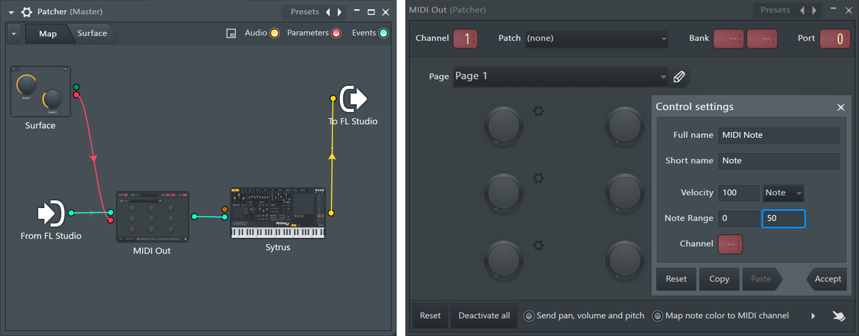
A MIDI note trigger button example:
- Add plugins - Add MIDI Out and a generator plugin with a MIDI input.
- Activate parameter(s) - Open MIDI Out and (Right-Click) on the knob on the top left and select 'Activate'.
- Configure MIDI settings - In the MIDI Out plugin, (Right-Click) on the same knob on the top left and select 'Configure'. Once a pop up window opens (as illustrated in the right side of the image above), open the dropdown menu labelled 'CC' and change it to 'Note'. In the note range settings, type in a MIDI note value on the input area on the right. Each musical note has its own corresponding MIDI value, and you can find a chart for that here.
- Add control - Go to the 'Surface' tab and create a button by clicking on the button with a plus icon and selecting 'Button'. Make sure that in the (Right-Click) 'Properties' menu the option 'Stay Down' is not selected.
- Connect controls - Return to the 'Map' tab and draw a connection from the button output to the MIDI Out input, as illustrated in the example image above.
- Connect MIDI - Draw a connection from the 'From FL Studio' MIDI output into the input of the MIDI Out plugin. This will allow other types of MIDI messages (Piano Roll, external keyboards) to also reach the generator plugin. Connect the output of the MIDI Out plugin into the MIDI input of the generator plugin.
- Connect audio - Draw a connection from the generator audio output into the 'To FL Studio' input.
- Test the setup - Go to the 'Surface' tab and press the button. You should now hear a sound, depending on which generator plugin you're using and which note you configured in the MIDI Out control settings.
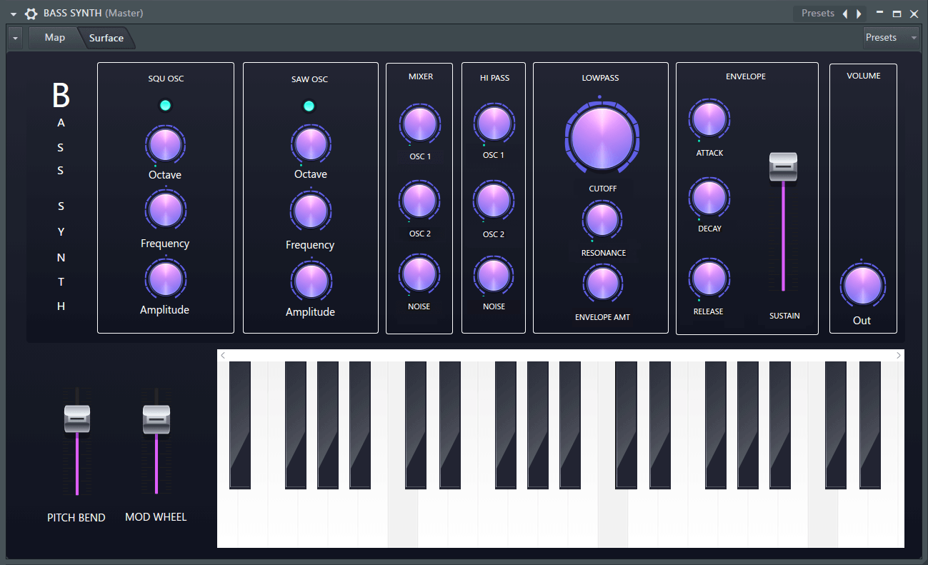
Creating Interfaces
You can make customized user interfaces for your patches by using Control Surface. Below is a list of some tips and good practices.
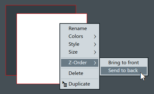
- Start from the bottom elements (bevels) and design the overall layout of the surface first. If you wish to move a bevel to the bottom later on, you can change the Z-Order (the order in which the bevels are stacked on top of eachother) by right clicking on the bevel and selecting Z-Order:
- Create sections for different control categories by using multiple bevels on top of eachother. Give the sections their own labels to keep things organized.
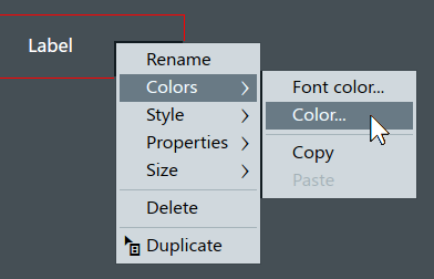
- Give your controls unique names, if you're designing the entire surface before making connections on the 'Map' tab. It will allow for easier identification when connecting to parameters. If you want multiple controls to have the same name, it's better to change this after connecting. Newly added labels will show on top of control labels, so you can also alter the surface name without affecting the actual control name by adding a label with a background color on top:
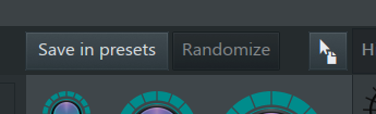
- Design the controls using Control Creator, and have a single copy of each control type you need on the surface for easy duplicating. You can save a preset in the Control Creator, or drag it directly onto a surface:
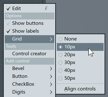
- If you want to get precise spacing in your design, enable grid snapping by right clicking in 'Edit' mode, and selecting the preferred pixel size:
- You can save Control Surface presets separately from patches. You can make templates for future projects, or create save points to return back to in case you're not happy with the changes you made.
Plugin Credits: Frederic Vanmol